Search the Community
Showing results for tags 'round moulding plane'.
Found 1 result
-
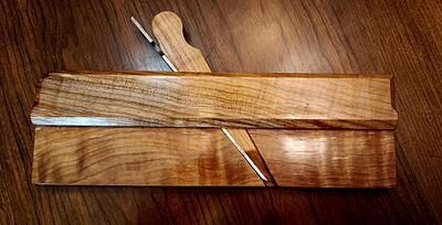
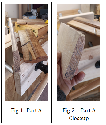
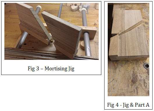
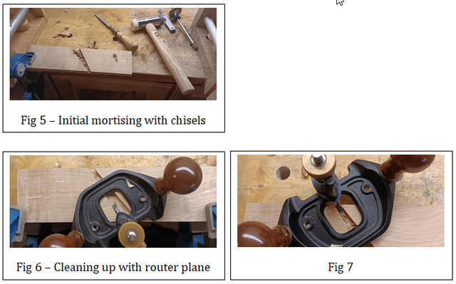
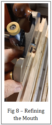
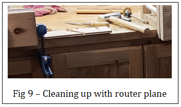
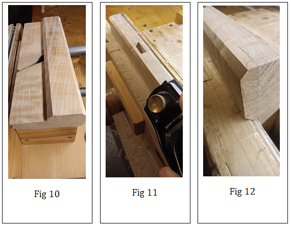
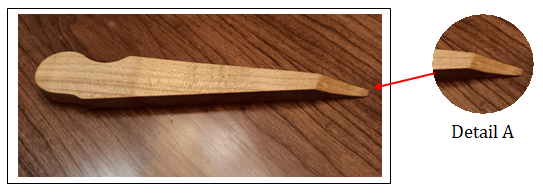
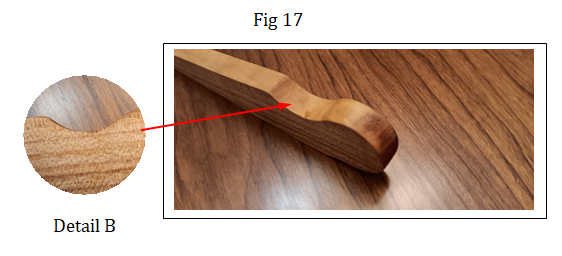
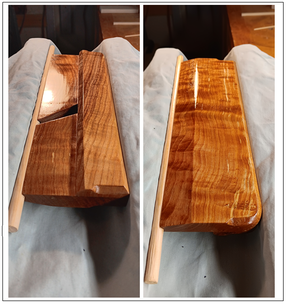
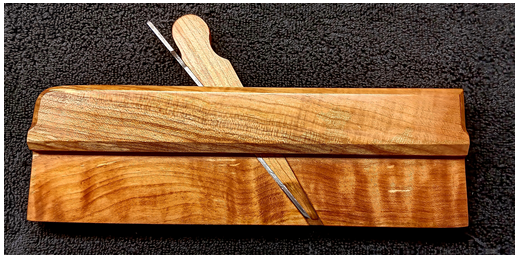
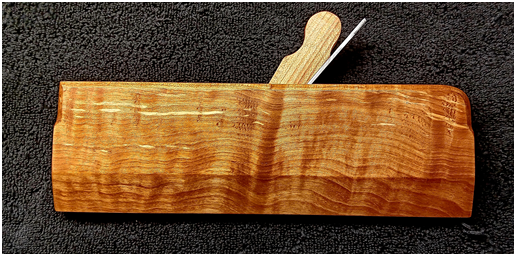
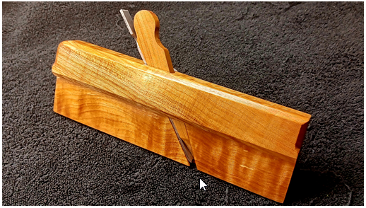
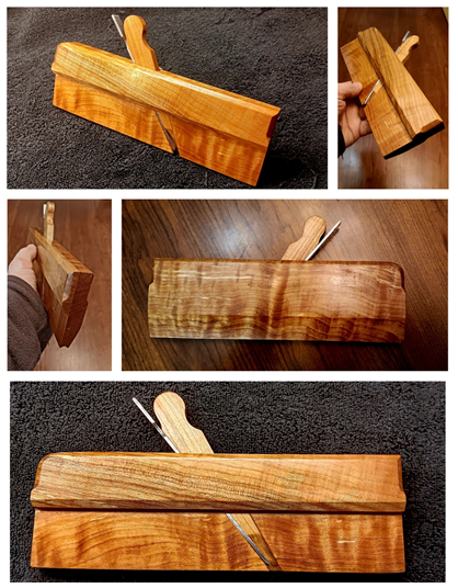
Introduction I enjoy doing most of my wood working projects with hand tools. I feel that I've become adept roughing stock with handsaws and squaring all four sides by hand planing. I've also become much better at joinery over the years with my favorite being handcut dovetails. One area that has intrigued me is creating mouldings with hollow and round moulding planes. Pursuing this has taken me down the road of making moulding planes. It has been a delightful pursuit. In addition, I make the blades or cutters and go through the whole heat treatment process. The Beginning I started by cutting two finished blanks out of Spalted Maple. These two blanks make the complete body of the plane. The first one (Part A) was milled to 5/8" thick x 3-1/8" high x 10" long and is the main body and left side in one piece. The second (Part B) was milled to 3/8" thick x 1-9/16" high x 10" long and is the right side that is laminated to the first piece. This plane will be a No. 2 ( 1/4") Round Moulding Plane. In Fig.1, it's mating plane, a 1/4" Hollow Moulding Plane sits on the right. It was used to make the 1/4" round groove as shown for the new plane on the left. When done this will make a matching set of 1/4” Round and Hollow Moulding Planes. See the closeup of the new plane's bottom in Fig 2. Mortising the Escapement Area Now it's time to mortise the escapement area for the blade's bed, cheek, throat, mouth, etc. I made this jig, see Fig 3 below, that I use for locating the bed angle at 50° and the wedge face at 60° on Part A. The jig has an adjustment screw that allows me to fine tune the mouth opening for Blade and Wedge. I can explain further how I use this jig if anyone is interested. Once I have the jigs placed where I want them (see Fig 4), I clamp them down on Part A to the bench and scribe the mortise cavity to be cut. Initially I cut the mortise cavity boundaries using my chisels (see Fig 5) Then I use my Lee Valley Veritas Large Router plane to excavate the cavity as shown in Fig 6 and 7. Here in Fig 8, I’m refining the mouth with the router plane. Fig 9 shows how I’ve clamped it to the bench while mortising. Laminating and Shaping Next in Fig 10, I laminated the Right Side (Part B) to Main Body (Part A). I then started chamfer detailing . In Fig 11 - 13, I am chamfering along the top edges and bottom edge of the Right Side (Part B). In Fig 14 & 15, I have done Stopped Chamfers for the front and back corners. The Wedge Next I shape the wedge Per Fig 16. As mentioned earlier the bed angle is at 50° and the wedge face at 60° on Part A. The wedge will be a 10° angle and is approx 6” long. Making the angle slightly larger initially then fine tuning to fit the mortised area is advisable. Detail A shows the curvature required for the shaving to climb up and out as you are planing. Fig 16 Per Fig 17, this is the notch, Detail B, for assisting in wedge removal. Blade This is the complete 1/4” round blade per Fig 18. I didn’t go into detail here with the whole process of shaping, heat treating, honing, etc. Again if anyone is interested and has questions please let me know. Fig 18 Finishing To start I coated all the plane body (except the bed) and the wedge with two coats of 50/50 cut Tung oil. Per fig 19. I let this cure for one week. Fig 19 Then I brush coated with two coats of Shellac and allowed to dry overnight. The actual sole is left only with the tung oil coating. After this, I French polished with shellac to make the grain “pop” per Fig 20. Fig 20 Finally per fig 21, I coated and buffed eveything with wood butter except the bed and bottom of the wedge. Here’s the completed 1/4” Round Moulding Plane per Fig 21 and Fig 22. Fig 21 Fig 22 Thanks for Looking! Cheers! MrRick

- 7 replies
-
- 3
-

-

-
- plane
- moulding plane
- (and 3 more)